1. VLAN
VLAN (Virtual Local Area Network) is a communication technology that logically divides a physical LAN into multiple broadcast fields. By defining the extended fields on the LAN data frame, this technology logically divides the physical network, so as to limit the forwarding range of the LAN data frame and narrow the broadcast domain. VLAN technology is mainly used in network equipment such as switches, routers and switches.
Click on the navigation bar: Configure- -> VLAN- -> Static VLAN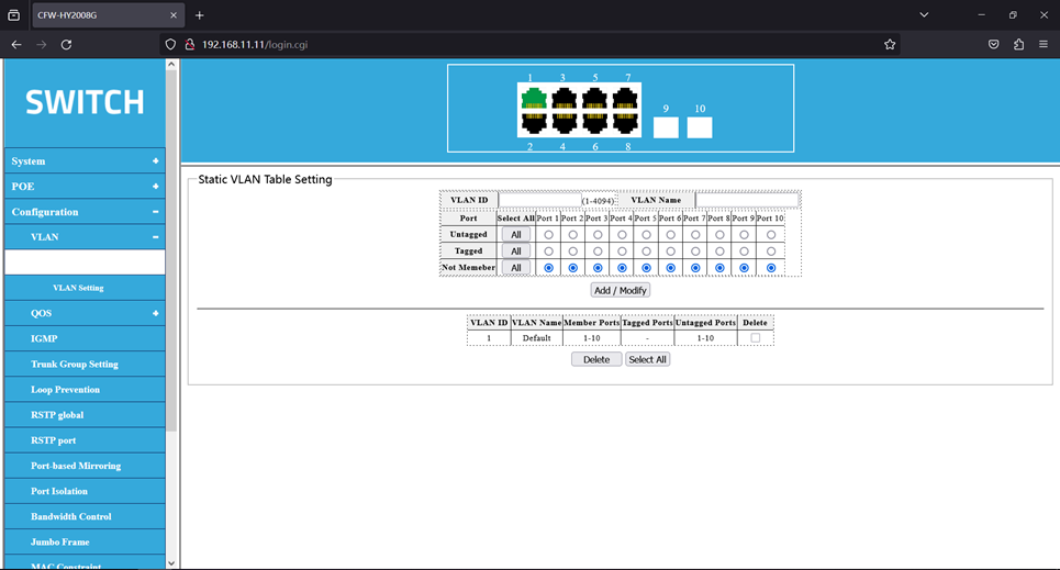
Click on the navigation bar: Configure- -> VLAN- -> VLAN Settings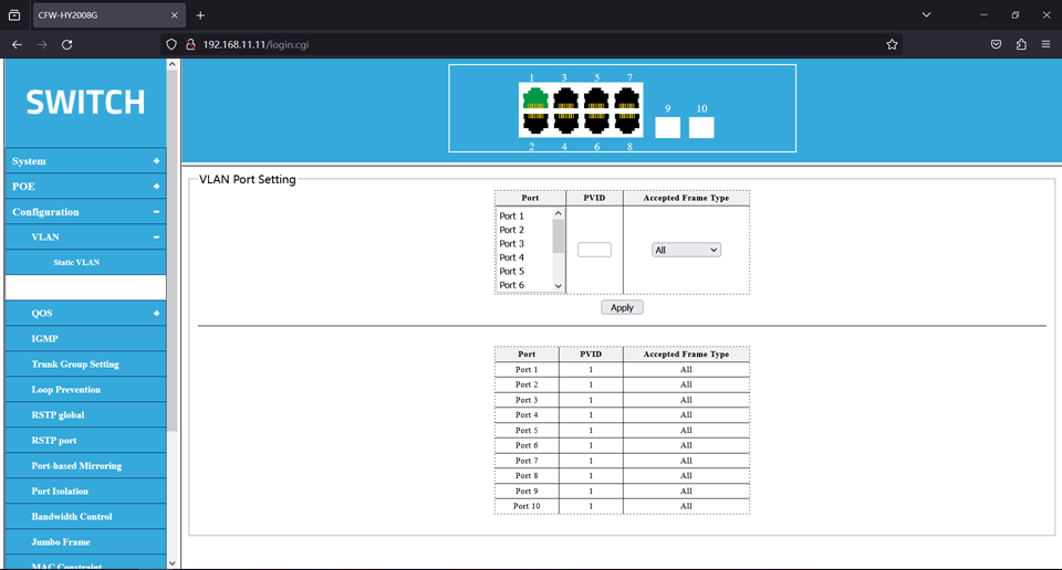
The VLAN is distinguished by the VLAN ID, and all the Untagged packets reaching the port are
labeled with the Tag of the port PVID.
Explain:
To set the VLAN ID before setting the port VID
The static VLAN set VLAN ID, range 1-4094.
If the Untagged port is Untagged port, the output data frame without tag information.
If the Tagged port is the Tagged port, the output data frame with tag information.
With no member port selected, it indicates that it is not a member port of the VLAN.
Note: Before deleting the VLAN, set the VID to 1 before removing the port using the VLAN.
2.Instance
As shown in Figure 11, the switch of an enterprise is connected to many users, and the same service user accesses the enterprise network through different devices. In order to ensure the security of communication and avoid broadcast storm, enterprises hope that users with the same business can access each other, and users with different business can not access directly. Interface-based VLAN division can be configured on the switch to divide the interfaces of user connections with the same service into the same VLAN. In this way, users belonging to different VLANs cannot directly communicate with each other at Layer 2, and users in the same VLAN can directly communicate with each other.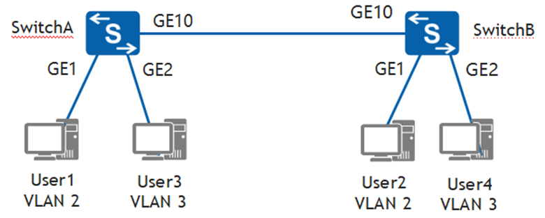
Create VLAN 2 and VLAN 3 on Switch A, and add the interfaces connecting users to the corresponding VLANs respectively. The configuration of SwitchB is similar to that of SwitchA and will not be described again. The link type between SwitchA and SwitchB is configured as trunk mode and the VLAN to be passed through, so that the same service users can communicate through SwitchA and
SwitchB.
As shown in Figure 12 below, create VLAN 2 on Switch A, add the corresponding interface to VLAN 2, and then click the <Add / Modify> button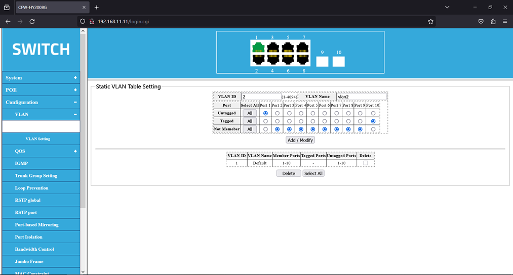
As shown in Figure 13 below, create VLAN 3 on Switch A, add the corresponding interface to VLAN 3, and then click the <Add / Modify> button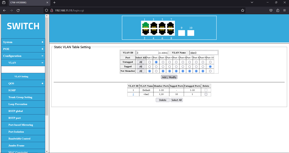
After setting the VLAN table, as shown in Figure 14 below: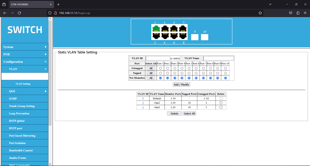
After setting up the VLAN table, you also need to set the port VID. Set the port 1’s port PVID to 2, and the port 2’s port PVID to 3. Select the interfaces and add them to the corresponding VLANs. The result is shown in Figure 15 below: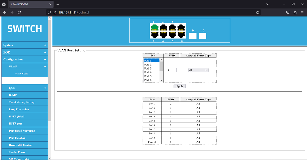
Test
User1, User2, User3, and User4 are configured on a network segment, such as 192.168.100.0/24. If no VLAN is configured, User1, User2, User3, and User4 can ping each other.
After configuring the VLANs, User1 and User2 can ping each other, but neither can ping User3 or User4. User3 and User4 can ping each other, but neither can ping User1 nor User2.
3.QoS
The QoS (Quality of Service) function is used to optimize the network performance and provide a better network service experience. The switch is based on port, 802.1P, DSCP, priority mode.
1.Priority Selection
Click on the navigation bar: Configure- -> QOS- -> Priority Selection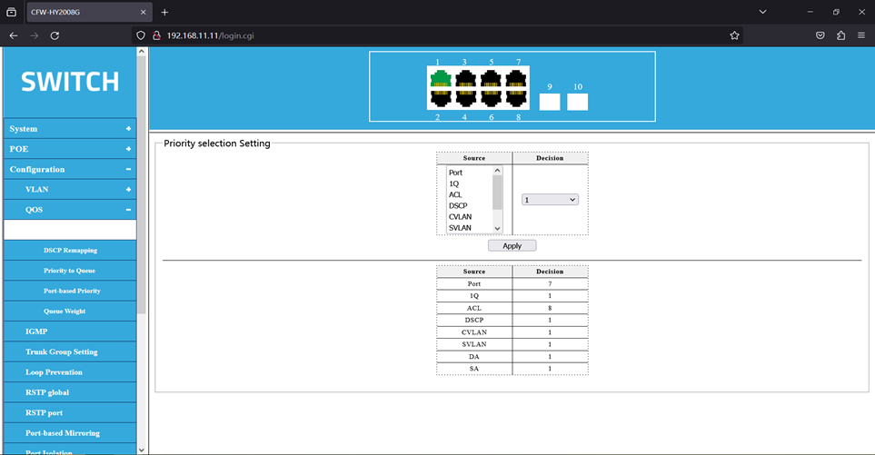
Explain:
Priority selection Set the priority of the priority source, which specifies the transmission queue of the frame from the priority source of the highest priority.
2. DSCP Remapping****
The DSCP gives a recommended definition of the IP DSCP field. IP packets are mapped to 8 priorities based on DSCP values (0-63).
Click on the navigation bar: Configuration- -> QOS- -> DSCP Remapping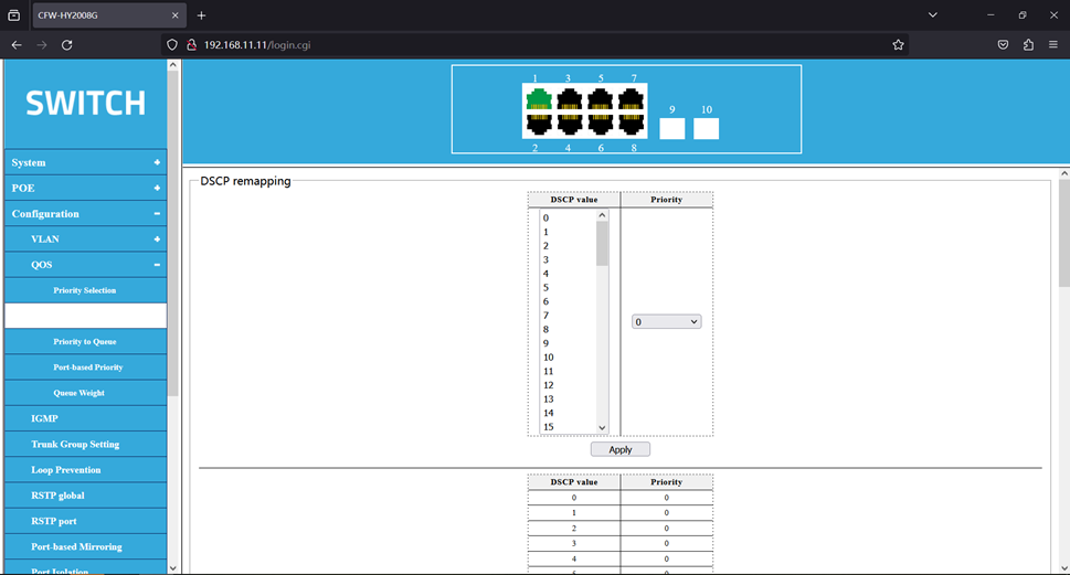
Explain:
Map the DSCP values to an internal priority
3.Priority to Queue
Mapping different priorities to different cohorts (4 queues)
Click on the navigation bar: Configure- -> QOS- -> Priority to Queue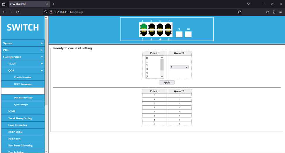
4.Port-based Priority
These packets are mapped to 8 different priority levels.
Click on the navigation bar: Configure- -> QOS- -> Port-based Priority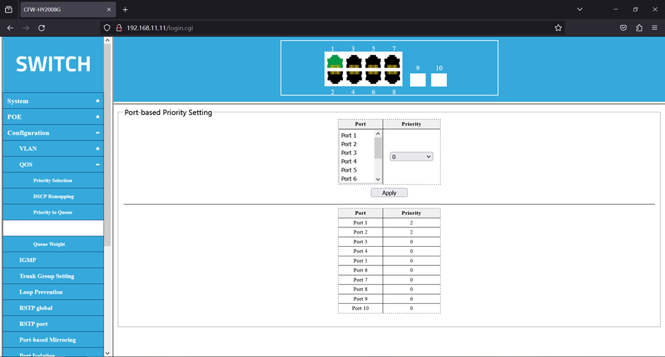
5.Queue Weight
Set the queue weights so that different queues get different scheduling priorities.
Click on the navigation bar: Configure- -> QOS- -> Queue Weights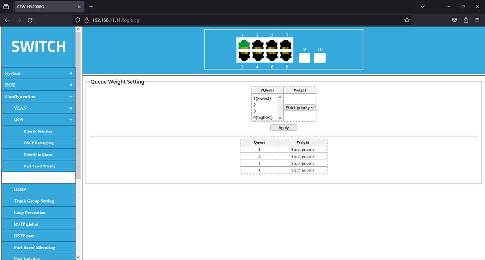
6.Instance 1
Port priority example
1、Connect the device by pressing the following topology.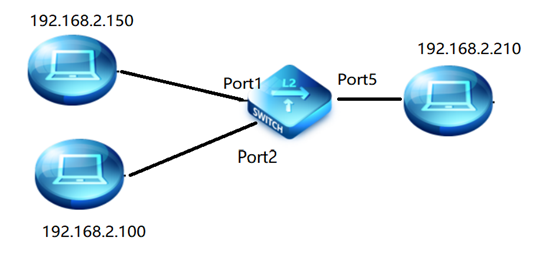
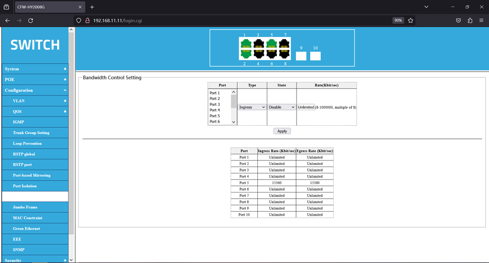
2、Easy to test and set ports 1 and 2 to 10M Full. Port 5 speed limit is 15 Mpbs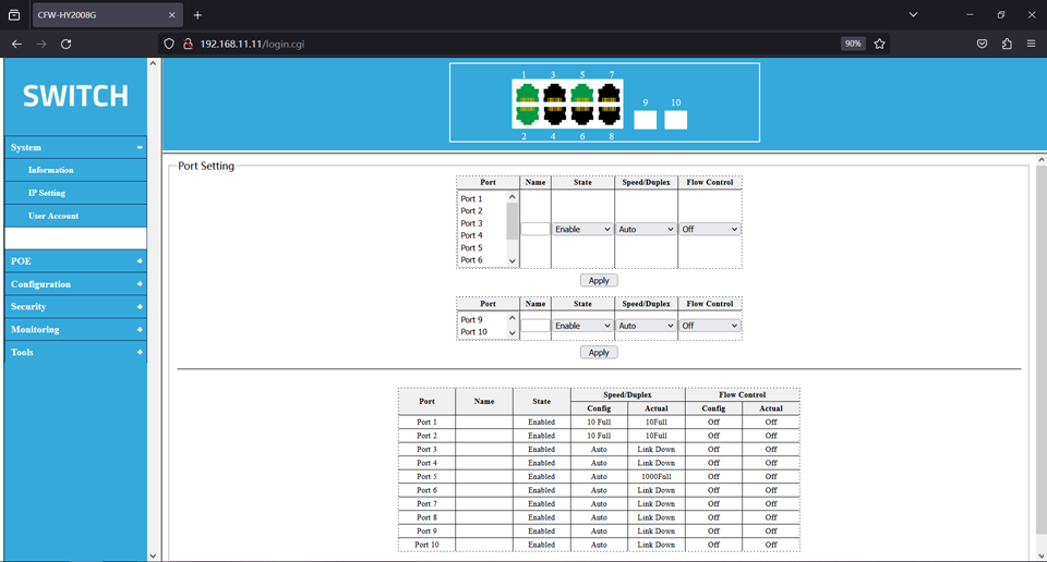
3、Open the test software to test the port 1,2 transmission rates when the port priority is not set. The transmission rates of ports 1 and 2 are constantly changing.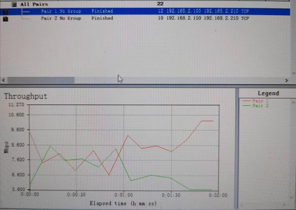
- Set port 1 priority to 6 and port 2 priority to
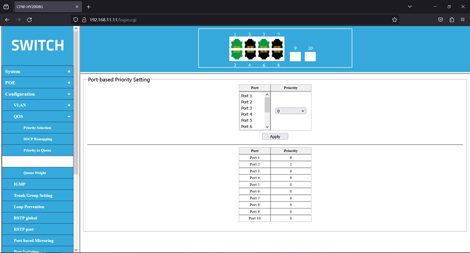
5、Open the test software and test the transmission rates of ports 1 and 2 after the port priority is set. Port 1 rates nearly 10Mbps, and port 2 has only 5Mbps.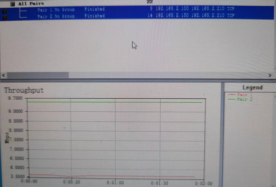
7.Instance 2
Example of queue weights
1、 In example 1, port 1 is connected to devices with IP 192.168.2.100, port 8 is connected to devices with IP 192.168.2.150, and port 5 is connected to devices 192.168.2.210.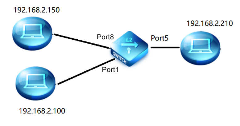
2、Set the priority to the queue mapping.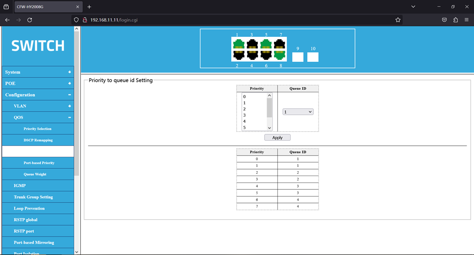
3、Set the port priority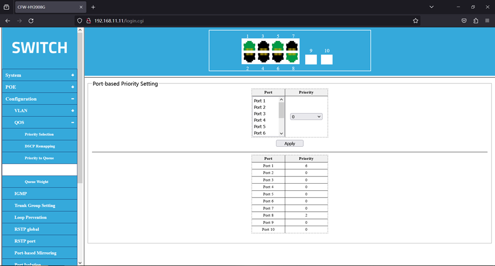
4、No queue weight is set, and the default strict priority is given.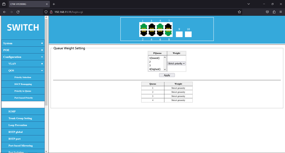
5, open the test software, dozen flow test. The result is shown below, the transmission rate of port 1 is about 980Mbps, and the transmission rate of port 8 is about 10Mbps.
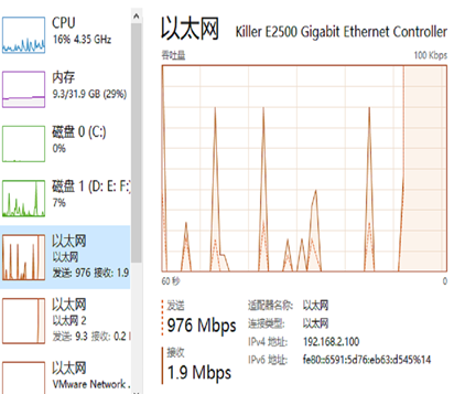
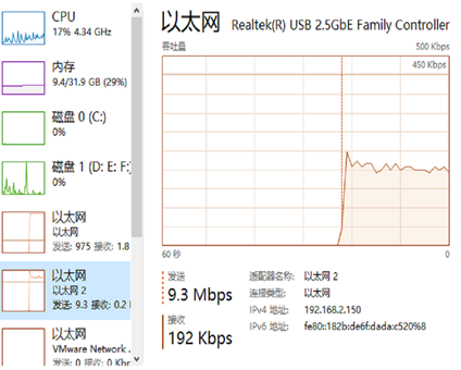

6、The modified queue weights are shown in the figure below.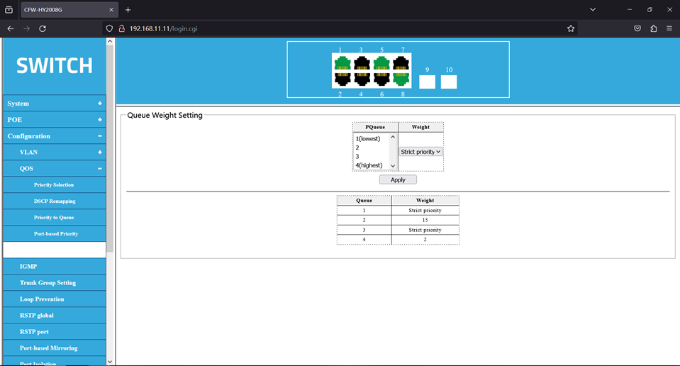
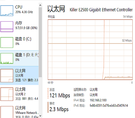
7、The retest results are shown in the following figure, and the transmission rate of port 8 becomes 880Mbps, and the transmission rate of port 1 becomes 121Mbps.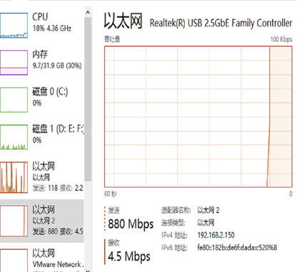


最后编辑:todaair01 更新时间:2025-03-20 16:52
